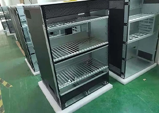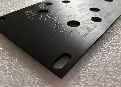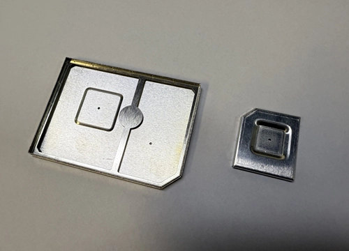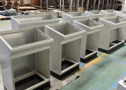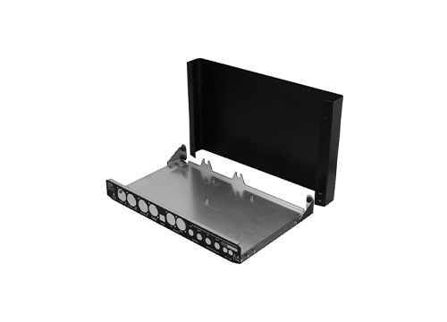

A sheet metal chassis prototype is more than a physical sample. For OEM engineers and product teams, it is an opportunity to verify whether the design can be fabricated consistently, assembled efficiently, and scaled to production without unnecessary cost or rework. A prototype that looks correct but has unresolved bend, hole, tolerance, fastening, or assembly issues can create problems when the design moves into mass production.
This is why sheet metal chassis fabrication should be reviewed from a Design for Manufacturing (DFM) perspective before the production design is frozen. The objective is not simply to confirm that one prototype can be built. It is to determine whether the design can be manufactured repeatedly using a stable process.
For applications requiring higher structural performance, thermal management, corrosion resistance, or reduced weight, aluminum can also be considered. Depending on the application, a heavy-duty aluminum sheet metal chassis may provide an effective combination of strength and weight, while a high-precision aluminum sheet metal chassis can be designed around tighter interface requirements and controlled fabrication processes.
The first purpose of a prototype is functional validation. Before mass production, the chassis should be tested against the requirements that matter to the final product rather than judged only by its visual appearance.
Start with overall dimensions and major interfaces. The prototype should confirm that circuit boards, power supplies, displays, fans, connectors, batteries, drives, brackets, and other internal components fit as intended. Any interface connecting the chassis to another assembly should receive particular attention.
Structural behavior is another important consideration. Check whether the chassis remains sufficiently rigid under expected handling, component loads, cable forces, installation forces, and other application-specific loads. If the product will be installed in a machine or vehicle, mounting behavior and vibration-related requirements should also be evaluated according to the applicable design specification.
The prototype should also validate manufacturing assumptions. Can the required bends be formed consistently? Are holes accessible to the intended tooling? Can fasteners be installed without interference? Are weld locations practical? Can the finished chassis be handled and inspected efficiently?
These questions turn a prototype into a DFM validation stage rather than simply a sample approval.
For OEM projects, HSJ Fabrication provides multiple fabrication processes that can support prototype development and production-oriented sheet metal work. Reviewing the company's fabrication products and capabilities can help determine which manufacturing process is appropriate for a particular chassis design.
Bends are among the most important features to review before a sheet metal chassis enters mass production. A design may be geometrically correct in CAD but difficult to manufacture if bend locations are too close to holes, other bends, edges, or existing features.
Hole-to-bend relationships deserve particular attention. A hole located too close to a bend can deform during forming or become difficult to produce consistently. The appropriate minimum distance depends on material, thickness, hole size, tooling, bend radius, and manufacturing process, so a universal number should not be assumed.
Internal and external bend radii should also be defined appropriately for the selected material and thickness. An overly small bend radius can increase forming difficulty or create cracking risks in some materials and tempers. The fabricator should confirm practical bend limits during DFM review.
Edge conditions should be considered at the same time. Sharp edges may create safety, handling, coating, or assembly problems. Deburring or edge treatment requirements should be specified where they affect the product.
| Feature | Potential Fabrication Risk | DFM Review Focus |
|---|---|---|
| Hole near bend | Hole distortion or forming interference | Check distance against material and tooling |
| Small bend radius | Forming difficulty or material cracking | Confirm material-specific bend capability |
| Closely spaced bends | Tool interference or difficult forming sequence | Review press brake access and sequence |
| Narrow flange | Tooling and dimensional control challenges | Confirm minimum practical flange size |
| Sharp exposed edge | Handling and assembly risk | Define deburring or edge treatment |
| Small internal feature | Limited tool access | Check cutting and forming accessibility |
For an aluminum chassis, these considerations become especially important because different aluminum alloys and tempers can behave differently during forming. A heavy-duty aluminum sheet metal chassis should therefore be reviewed according to the actual alloy, thickness, bend geometry, and forming process rather than using generic sheet metal rules.
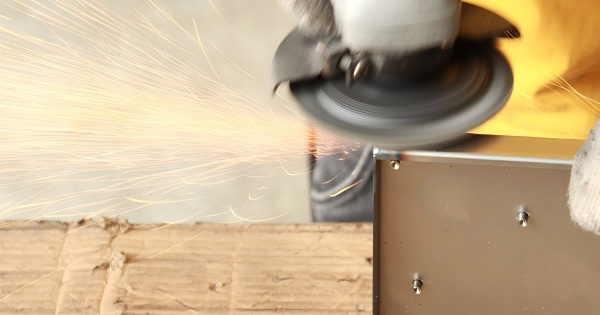
A chassis is rarely a standalone component. It usually provides mounting locations for other parts, which means fastening and assembly features should be considered during the prototype stage.
Common options include threaded holes, PEM-style fasteners, rivets, weld nuts, studs, screws, and welded brackets. Each method creates different requirements for access, tooling, hole size, flange space, and assembly sequence.
For example, a threaded feature may be easy to machine or form in one location but difficult to reach after several panels have been bent. A fastener that appears accessible in an isolated CAD model may become inaccessible once the complete chassis is assembled.
Assembly datums should also be established early. A datum strategy gives engineering and manufacturing teams a consistent reference for locating critical holes, mounting surfaces, connectors, and components.
For welded chassis designs, define which welds are structural and which are primarily for positioning or enclosure construction. Excessive welding can introduce distortion and unnecessary production time. The design should therefore identify functional weld requirements rather than assuming that more welds automatically produce a better chassis.
During prototype assembly, record where tools, operators, cables, and components interfere with one another. These observations can reveal problems that are difficult to identify from a drawing alone.
Individual dimensions may each fall within their specified tolerances while the completed chassis still fails to fit correctly. This is a tolerance-stack problem.
Consider a chassis containing several mounting holes for a circuit board. The location of each hole may be acceptable individually, but the combined dimensional variation can cause the board or mating component to bind during assembly.
Critical interfaces should therefore be analyzed as systems rather than as isolated dimensions. Identify the features that determine component position and establish which dimensions actually control fit.
This is especially important for a high-precision aluminum sheet metal chassis, where multiple machined, cut, bent, or assembled features may interact. High precision should be applied where it provides functional value rather than indiscriminately tightening every dimension.
A practical DFM review should distinguish between:
Critical dimensions that directly control assembly or function.
Reference dimensions that communicate design intent.
General dimensions where normal fabrication variation is acceptable.
Features requiring secondary machining or inspection.
Overly tight tolerances can increase fabrication and inspection costs. Conversely, tolerances that are too loose at critical interfaces can create assembly problems. The goal is a tolerance scheme that matches the actual functional requirements.
Before approving the final production design, the prototype should be evaluated from both engineering and manufacturing perspectives.
First, confirm physical fit. Install the actual components wherever practical rather than relying entirely on nominal CAD dimensions. Check connectors, cable routing, fasteners, covers, access panels, and service areas.
Next, review the manufacturing process. Confirm that cutting, bending, welding, fastening, finishing, and inspection operations can be performed consistently. If a feature requires manual adjustment or excessive rework during prototype production, it should be investigated before the design is released for production.
Material utilization should also be reviewed. A small geometry change can sometimes reduce scrap or simplify the flat pattern without changing the finished product's function.
For aluminum chassis projects, surface treatment should be checked as well. Anodizing, powder coating, or other finishes can affect dimensions, appearance, grounding areas, and assembly interfaces. Any areas that must remain uncoated should be clearly identified.
The production review should also consider packaging and handling. Large or thin sheet metal components may require additional protection to prevent scratches, deformation, or cosmetic damage during transport.
Before design freeze, it is useful to document all prototype changes and classify them as engineering changes, manufacturing improvements, or cosmetic adjustments. This creates a clear transition from prototype sheet metal chassis fabrication to repeat production.
A complete drawing package is one of the most effective ways to reduce ambiguity during production. The manufacturer should not have to infer critical requirements from a 3D model alone.
The 2D drawing should identify material grade, thickness, overall dimensions, critical tolerances, bend information, hole sizes and locations, threads, weld requirements, surface finish, and inspection requirements.
The drawing should also make the relationship between formed features clear. Bend direction, bend radius, and important reference datums should be defined where they affect manufacturing or assembly.
The BOM should identify every purchased and fabricated component required for the chassis assembly. Fasteners, inserts, brackets, gaskets, hardware, and other secondary components should not be left ambiguous.
For production, revision control is equally important. The released drawing, CAD model, BOM, and manufacturing instructions should reference the same revision. Otherwise, a supplier may manufacture from an outdated file even though the engineering team has already approved a newer design.
HSJ Fabrication can support projects involving cutting, bending, welding, and other sheet metal processes. For OEM buyers moving from prototype to production, providing a complete drawing and BOM package allows the fabrication process to be evaluated against the actual production requirements.
If your chassis prototype is approaching design freeze, you can contact HSJ Fabrication with the CAD files, drawings, BOM, material requirements, and production quantities for a fabrication review.
A successful prototype sheet metal chassis should prove more than dimensional correctness. It should demonstrate that the design can be cut, bent, welded, fastened, finished, inspected, and assembled consistently at production scale.
The most important DFM checks involve bend geometry, hole placement, edge conditions, fastening access, weld strategy, assembly datums, tolerance stacks, material selection, surface finish, and documentation. Addressing these issues before design freeze can reduce engineering changes and avoid preventable production rework.
For demanding applications, material selection also deserves careful consideration. A heavy-duty aluminum sheet metal chassis may be appropriate when structural performance and weight are both important, while a high-precision aluminum sheet metal chassis may be better suited to applications with demanding component interfaces.
Ultimately, effective sheet metal chassis fabrication depends on designing for the manufacturing process from the beginning. A detailed DFM review with an experienced fabrication partner can help transform a workable prototype into a repeatable production design.
The prototype should validate fit, function, structural behavior, assembly, manufacturability, and critical interfaces before the design is released for mass production.
Important features include bend locations, bend radii, hole-to-bend distances, flange sizes, edge conditions, cutouts, fastener locations, and tool-access requirements.
Yes, aluminum can be suitable when the selected alloy, thickness, forming method, and structural design meet the application's requirements. A heavy-duty aluminum sheet metal chassis should be evaluated based on actual load and environmental conditions.
It can be appropriate when critical mounting interfaces, connector locations, component alignment, or assembly relationships require controlled dimensional accuracy.
Several individually acceptable dimensional variations can accumulate and prevent components from fitting correctly. Critical interfaces should therefore be evaluated as a complete dimensional system.
A typical production package should include the released 2D drawing, 3D CAD model, BOM, material specifications, surface-finish requirements, critical tolerances, welding and fastening requirements, and controlled revision information.

 English
 日本語
日本語 français
 Deutsch
 Español
 italiano
 русский
 português
 Svenska
 Ελλάδα
 Nederland